
MBro - Vision System
MBro-Vision System is an integrated system which can detect and analyze defects and malfunctions in product, including paper
and fiber, manufactured by a high-speed manufacturing facility, to ensure the quality of the products and the efficiency of the facility.
It collects the full live image data of the products, which are transferred at high speed, with an ultra-speed camera and analyzes
and stores the data by using ultra high speed network and utility.
It provides the live data in various formats to an operator so the operator could utilizes the data for the improvement of the facility.
Since MBro-Vision System produce a “real-time alarm’ signal when its high-speed image analyzer detects a defect on the
product which is very high speed moving, it could prevent to be aggravated the quality of products which are transferred at high
speed and brought significantly lower the production costs.
The system can be utilized in diverse manufacturing circumstances including the manufacturing of paper, fiber, steel and tissue.
Also, it is relatively easy to install and operate.
MBro - Vision System Features
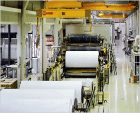 |
- Utilized system for analysis “Web break” and “Defects” (2.56mm²~ ) - Produce alarm signal and store the detecting of defects live image by real time analysis for high speed moving target (100fps) - It gives simplicity to operate and install |

MBro Vision Analyzing System is consisted 3 kind of configuration according to be detected size of “DEFECTS” by area scan.
- System for detecting big size (2895mm²) of “defects”:
Can be configured to produce alarm for “Web Break”
- System for detecting medium size (8.56mm²) of “defects”:
Can be configured to produce alarm for “defects”
- System for detecting small size (2.56mm²) of “defects”:
Can be configured to produce alarm for “defects”
- Image of “defects”:

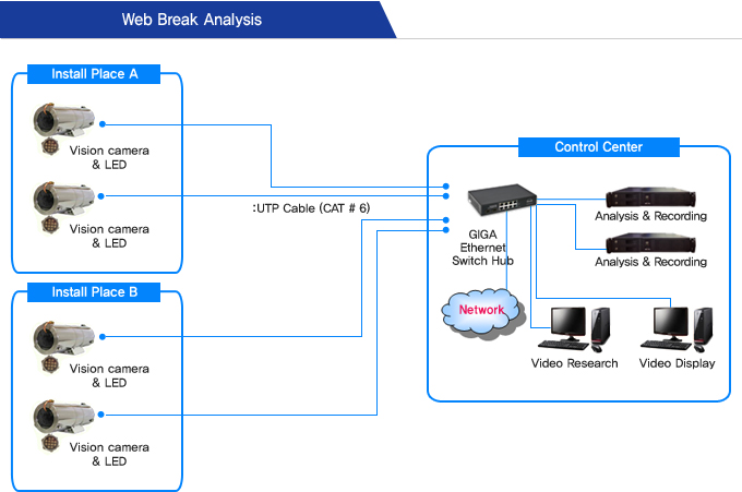
1. Created event log and alarm after analyzing the initiating point of Web Break
2. Transfer Alarm signal to control room and alarm tower or other facility
3. Use industrial high speed camera : 0.3M (VGA), 86fps, CCD
4. IR LED Strobe : 86fps, maximum pulse power : 9watt/LED
5. Maximum Paper Speed:
2. Transfer Alarm signal to control room and alarm tower or other facility
3. Use industrial high speed camera : 0.3M (VGA), 86fps, CCD
4. IR LED Strobe : 86fps, maximum pulse power : 9watt/LED
5. Maximum Paper Speed:
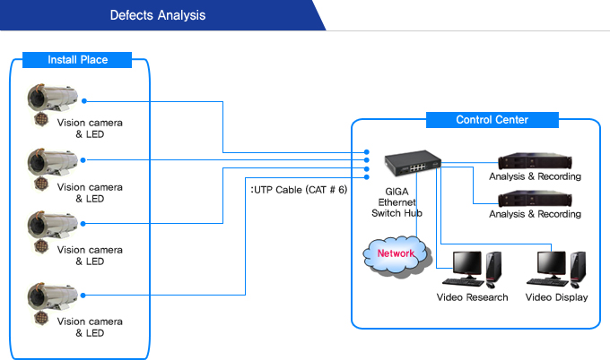
1. Created event log and alarm after analyzing detecting a defects of analysis algorithm
2. Transfer Alarm signal to control room and alarm tower or other facility
3. Use industrial high speed camera : 1.3M (HD), 30fps, CCD
4. IR LED Strobe : 30fps, maximum pulse power : 16watt/LED
5. Maximum Paper Speed:
2. Transfer Alarm signal to control room and alarm tower or other facility
3. Use industrial high speed camera : 1.3M (HD), 30fps, CCD
4. IR LED Strobe : 30fps, maximum pulse power : 16watt/LED
5. Maximum Paper Speed:

Event Properties & Standard value
1. Input value of properties for “defect analyzing”
- Area (o) : Input number of pixel according to “defect size”
Consist of pixel by “defect size”: 1 ~ 10 pixel x 1 ~ 10 pixel
ex) 2pixel x 2pixel = 1.56mm x 1.38mm
- Height (o) : Recognized “Area”
- Width (o) : Recognized “Area”
2. Input value of properties for “defect & web break analyzing”
- Bright/Dark (o)
A grade of bright & dark pixels to be compared standard image
Adjustment sensitivity of bright & dark to grades 1 ~ 90
- Aspect Ratio (x) - Relative Brightness (o) Express relation of light density level of Camera Light (LED) and Brightness of defect image Establish the best working condition of Camera Light (LED) - Relative Contrast (o) Relations of standard deviation to be expressed brightness and darkness of the defect pixel by produced Camera Light (LED) Establish the best working condition of Camera Light (LED) - Camera Positioning (o) : Input on set-up sheet

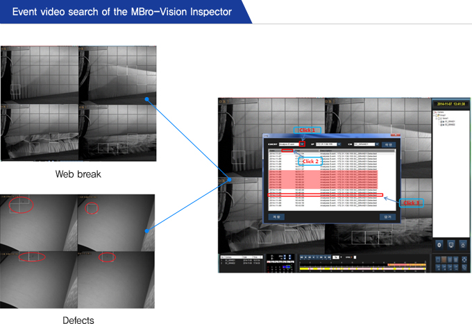
1. Click Event list
2. Click analysis Event
3. Pop-up the Event list
4. Double click of the working camera to be checked the Events
2. Click analysis Event
3. Pop-up the Event list
4. Double click of the working camera to be checked the Events
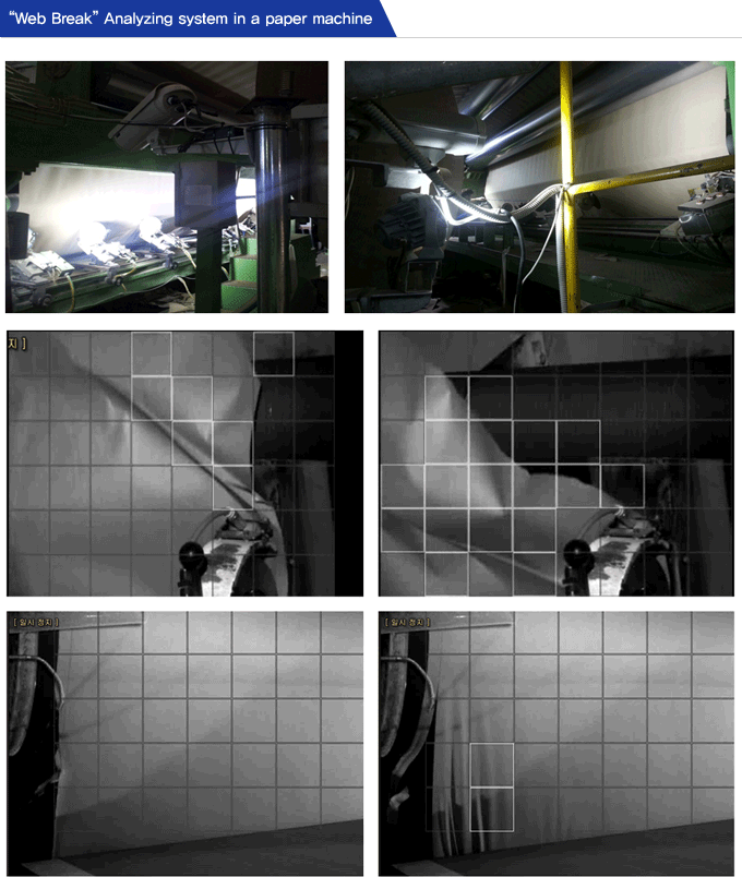
“Web Break” Analyzing Image
◆ Working point: “WINDER”
◆ Line Speed: ~ 2100m/min
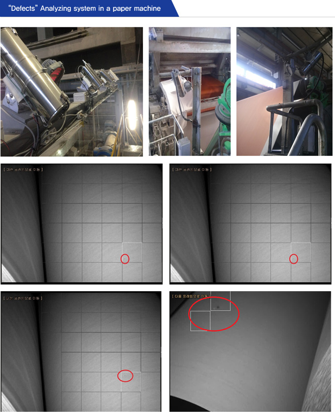
“Defects” Analyzing Image
◆ Working point: “CALENDER”
◆ Line Speed: ~ 2100m/min


